What is UART
>
Do you still remember the printers, mice, andModemIs that okay? They all have huge and bulky connectors and thick cables, and must be screwed onto your computer. These devices communicate with computers using the UART protocol. Although USB has almost completely replaced old cables and connectors, UART is definitely not outdated. You will find that many projects currently use UART GPS modulesBluetooth moduleAndRFIDConnect the card reader module and other components to the Raspberry Pi,ArduinoOr othermicro controllerUp there.
Universal Asynchronous Receiver/Transmitter, commonly known as UART. It converts the data to be transmitted between serial communication and parallel communication. As a chip that converts parallel input signals into serial output signals, UART is usually integrated into the connections of other communication interfaces.

It's not likeSPILike I2Ccommunication protocolIt is an independent physical circuit or IC in the microcontroller.
The best thing about UART is that it can transmit data between devices using only two wires, and the principle behind UART is easy to understand.
Introduction to UART Communication
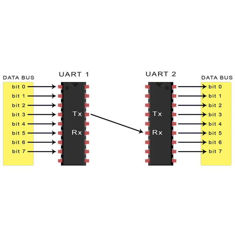
In UART communication, two UART directly communicate with each other. Sending UART converts parallel data from control devices such as CPU into serial form and sends it serially to receiving UART, which then converts the serial data back to the parallel data of the receiving device. Only two wires are needed to transmit data between two UART devices. Data flows from the Tx pin of the sending UART to the Rx pin of the receiving UART:

UART sends data asynchronously, which means that there is no clock signal to synchronize the bit output of the sending UART with the bit sampling of the receiving UART. Sending UART is not a clock signal, but rather adding start and stop bits to the data packet being transmitted. These bits define the beginning and end of the data packet, so the receiving UART knows when to start reading the bits.
When the UART detects the start bit, it begins to receive signals calledBaud rateRead the input bit at a specific frequency. Baud rate is a measure of data transmission speed, expressed in bits per second (bps). Two UART devices must run at approximately the same baud rate. The baud rate difference between sending and receiving UART can only be about 10%.
Both UART must also be configured to send and receive the same packet structure.

How UART works
UART data transmission relies on the UART bus, which is used to send data to UART through other devices such as CPU, memory, or microcontroller. Data is transmitted in parallel from the data bus to the UART transmitter. After obtaining parallel data from the data bus through UART, it will add a start bit, parity bit, and stop bit to create a data packet. Next, the data packet is serially output bit by bit on the Tx pin. The UART receiver reads data packets bit by bit on its Rx pin. Then, the receiving UART converts the data back to parallel form and removes the start bit, parity bit, and stop bit. Finally, the UART receives the data packet and transmits it in parallel to the data bus at the receiving end

The data transmitted by UART is organized into packets. Each data packet contains 1 start bit, 5 to 9 data bits (depending on UART), optional parity bits, and 1 or 2 stop bits:

Start position
When the UART data transmission line is not transmitting data, it usually remains at a high voltage level. To start data transmission, the UART sends the transmission line from high level to low level for one clock cycle. When the UART detects a high to low voltage transition, it starts reading bits from the data frame at the baud rate.
Data box
The data box contains the actual data to be transmitted. If parity is used, it can be 5 to 8 bits long. If parity bits are not used, the data frame can be 9 bits long. In most cases, data is first sent in the least significant bit.
Parity check bit
Parity check describes the uniformity or odd number of a number. Parity check bit is a method used by UART to determine if any data has changed during transmission. Data may change due to electromagnetic radiation, mismatched baud rates, or long-distance transmission. After receiving UART data frames, it calculates the number of bits with a value of 1 and checks whether the total number is even or odd. If the parity bit is 0 (even check), then the 1 bit in the data frame should total to an even number. If the parity bit is 1 (odd check), then the 1 bit in the data frame should total to an odd number. When the parity bit matches the data, UART knows that there are no errors in the transmission. But if the parity bit is 0, however, 1 bit should total to an odd number; Or if the parity bit is 1 and 1 bit should total to an even number, then the bits in the data frame have changed.
Stop position
In order to notify the end of data packet transmission, the UART transmitter will drive the data transmission line from low voltage to high voltage for at least two bits of duration.
UART transmission steps
1. Send UART to receive data in parallel from the data bus:

2. Send UART to add the start bit, parity bit, and stop bit to the data frame:

3. The entire data packet is transmitted serially from the sending UART to the receiving UART. Receive UART to sample the data line at a pre configured baud rate:

4. Receive UART discard the start bit, parity bit, and stop bit in the data frame:

5. Receive UART to convert serial data back to parallel and transmit it to the data bus at the receiving end:

Advantages and disadvantages of UART
No communication protocol is perfect, here are some advantages and disadvantages that can help you determine if they meet the needs of your project:
advantage
Only use two wires
No clock signal required
There is a parity check bit
As long as both parties have set it up, the structure of the data packet can be changed
There is complete documentation and extensive use
shortcoming
The maximum size limit for data frames is 9 bits
Does not support multiple subordinate or master systems
The baud rate of each UART must be within 10%